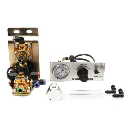
Hendrickson lift axle control valve diagram
Face plate measures 2. Assembled in USA.
OF DE. Effective date : Year of fee payment : 4. Year of fee payment : 8. Year of fee payment : A control system for a lift axle suspension wherein two or more axle suspensions are mounted on a vehicle frame and a liftable axle is automatically raised or lowered depending on the load on another of the axle or axles. An override to the automatic lift system is provided when the vehicle is fully loaded to lift a liftable axle selectively for a limited, relatively short period of time to assist in maneuvering the vehicle.
Hendrickson lift axle control valve diagram
Compressor - Twin Cylinder. Compressor - Special Cylinder. Compressor - Stand Alone. Compressor Cylinder Head. Multiple Circuit Protection Valve. Governor and Unloader. Charging Valve. Safety Valve. Protection Valve. Triple Protection Valve. Air Dryer - Single Chamber. Air Dryer - Twin Chamber.
The controller is coupled to the electrical input 80 for the solenoid valve 56 through the control output line The products are designed specifically to handle the rigorous environment and general abuse associated within on-highway, off-highway and specialty applications.
Hide thumbs. Table of Contents. Quick Links. Product Description. Important Safety Notice. Parts List.
Need Help? The complete 20, pound capacity suspension system and kit are currently available for truck mount configuration only. A kit version is also available for 13, pound capacity in truck or trailer mount configurations. Buy Now Terms and Conditions. Search for:.
Hendrickson lift axle control valve diagram
Need Help? The axle is rated based on the lowest capacity component fitted to that axle. The installer should check that the tire and rim combination meets the load requirements. The rating information on the Hendrickson vendor provided hubs can be found at:. For KIC wheel ends standard fit : www. A non-steerable lift axle that is not raised when turning, especially in a tight corner, will scrub concrete and impose high lateral stress on the wheels and chassis components of your vehicle.
5 letter word starting with div
A normally open inlet port 76 is open to the atmosphere and allows atmospheric pressure to pass through the valve 60 and into the lift air springs 44 in the absence of pressure in pipe IPU Pedal Unit. Each AIRman product is designed to meet or exceed OEM standards and meet the widest range of temperature, chemical resistance, sludge and lifecycle performance. The products are designed specifically to handle the rigorous environment and general abuse associated within on-highway, off-highway and specialty applications. This system relies on the operator to make judgments and to exercise that judgment. The control system according to the invention can be employed with a conventional air control system for raising and lowering the liftable axle suspension. The invention provides an improvement in the load-detecting means which comprises electrical sensing means, and the control means has an electrical circuit to control the activation means responsive to a signal from the electrical sensing means. Air Dryer with Purge Tank. Electrical Cable. The invention will now be described with reference to the accompanying drawings in which:. Privacy Policy Terms of Use. Compressor - Twin Cylinder.
Always use Hendrickson Genuine Parts for the best quality in the industry.
SideWings - EndSkirt. Contact vehicle manufacturer for additional service information. To this end, controlled air pressure is provided to the control air inlet to the control valves 82 through pipes 84, T- connector 86 and pipes Thus, the invention provides a system for automatically controlling the position of a liftable air spring suspension, yet allows the operator to interface with the control system to selectively raise the axle for short periods of time to enhance the maneuverability of the vehicle. Retarder Control Retarder Valve. Alternatively, the first suspension can be a mechanical suspension, such as a leaf spring, and the means to detect the load on the first axle can be a strain gauge. Hydraulic Brake Chamber. Section 13 Troubleshooting Guide. Observe if lift axle deploys. This condition will continue for the extent of the time-delay TD S , for example, one minute. An outlet pipe 70 connects the control valve 60 with the air lift springs 44 through T- connector 72 and pipes CAC en. Transmission Solenoid Valve. A control system for a lift axle according to claim 16 wherein said relatively short period of time is substantially longer than the delay in the operation of said actuation means.


You will not prompt to me, where I can find more information on this question?
I am sorry, it does not approach me. Perhaps there are still variants?