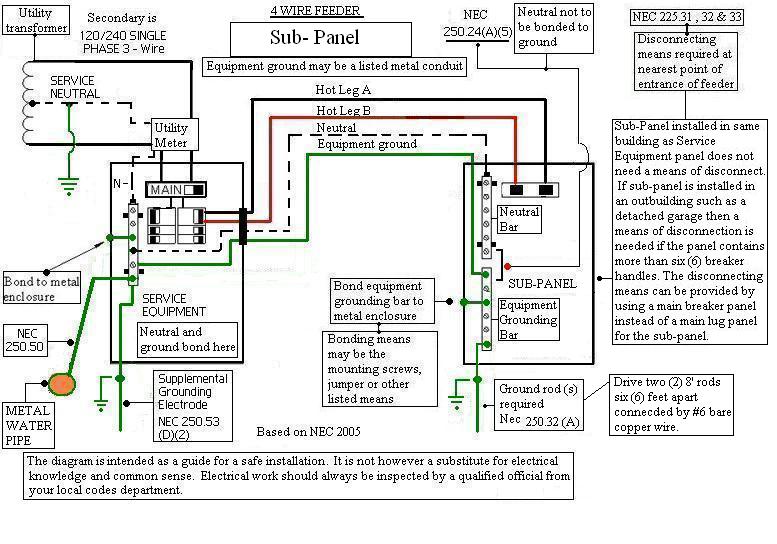
Residential 100 amp sub panel wiring diagram
A main panel is the first line of defense against the electric surges and other faults short circuitoverload, over current etc. The main panel is directly connected to the feeder cables from the energy meter and distribution transformer mounted on the utility pole.
Forums New posts Search forums. Media New media New comments Search media. Members Current visitors New profile posts Search profile posts. The Alliance. The Store. Log in Register.
Residential 100 amp sub panel wiring diagram
.
To get only V supply voltage, you would have to connect the Hot 1 as line in the black color to both hot lugs in the subpanel through jumper wire see fig. Joined Dec 18, Messages Where is that defined?
.
Typically, while wiring a subpanel, an electrician will first extend a feeder wire from the main panel to the subpanel. The feeder breaker is then installed in the open double slot of the main service panel by the electrician. There are certain ways of Amp Panel wiring which are explained below. However, it is always advisable to call an electrician to avoid any risk. While installing a subpanel, an electrician generally first runs a feeder cable to the subpanel from the main panel.
Residential 100 amp sub panel wiring diagram
A main panel is the first line of defense against the electric surges and other faults short circuit , overload, over current etc. The main panel is directly connected to the feeder cables from the energy meter and distribution transformer mounted on the utility pole. In residential applications, three wires i.
Intel hd graphics driver windows 7 32 bit download
It is because we run only V circuits where white neutral is no longer needed. Make sure that you have good lightning when installing a subpanel you could use a battery operated light. You may use 6 gauge wire for 60A circuit breaker from the main panel to the subpanel. Related Posts:. Depends on how much of the SER is actually in insulation. Do I need those? Joined Oct 14, Messages 4 Location Vancouver. Where is that defined? In the fig below, both miniature circuit breakers and GFCI circuit breaker are connected to to power up the load circuits via Hot, Neutral and Gerund wire. The new panel would be on the inside of the garage on the same wall as the main panel which is on the outside of the wall.
Updated on January 15, Most contemporary homes have what is now commonly referred to as an electrical panel or the service panel.
It is because we run only V circuits where white neutral is no longer needed. The Alliance. You should upgrade or use an alternative browser. So basically follow the wiring diagram in the first picture correct? The new panel would be on the inside of the garage on the same wall as the main panel which is on the outside of the wall. Also never any worry about voltage drop, the Cu is a better, more efficient conductor per unit weight. Measuring Instruments. You can also like and follow our social media networks below, or subscribe with your email to receive premium engineering articles in your mailbox. So the run to the new panel would be maybe 4 feet. JavaScript is disabled. Search titles only. As shown, we need all the three wires i. Table of Contents Toggle. Would I run the neutral and Ground wires from this bus bar to the new panel? The reason i like Cu especially for short runs are that you can get all the colors red, white black at Home D at least my local one "by the foot" which is pretty reasonable for a 5 foot run, probably need feet of wire per conductor.


In my opinion you are not right. I can defend the position.
It agree, it is an amusing phrase
What nice idea