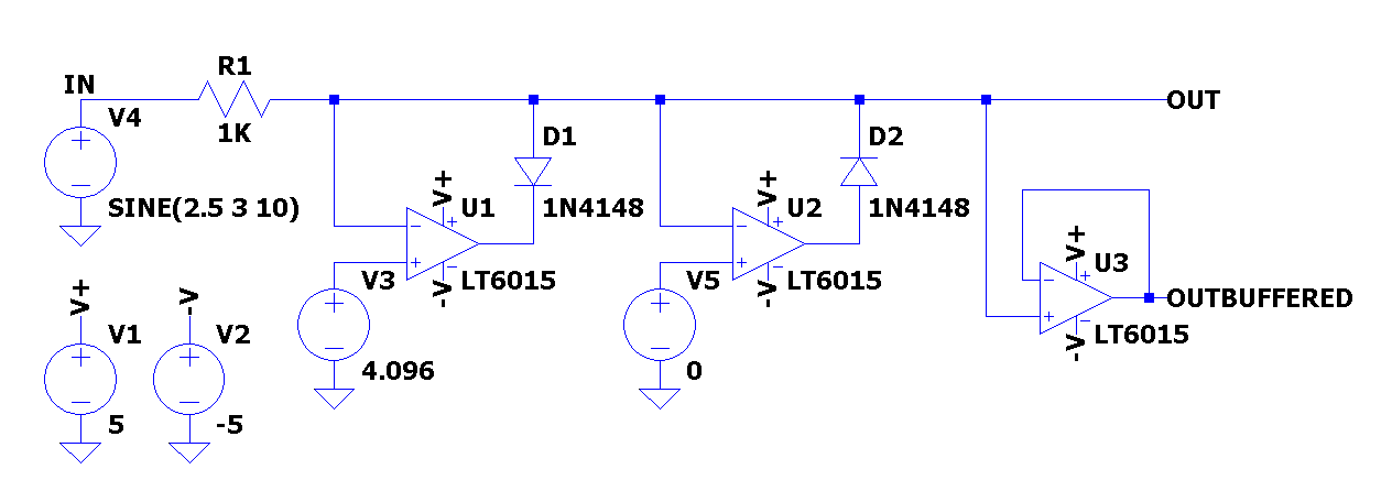
Precision op amp clamp circuit
Welcome, Guest.
Sp in ni ng Spark. This file contains additional information, probably added from the digital camera or scanner used to create or digitize it. If the file has been modified from its original state, some details may not fully reflect the modified file. Contents move to sidebar hide. File Talk.
Precision op amp clamp circuit
.
This topic This board Entire forum Google Bing. Quote from: Terry Bites on March 13,pm.
.
Explore the intriguing world of voltage clamp circuits, their principle, components, and broad applications in electronics and neuroscience. The concept of voltage clamping is integral to the field of electronics and neuroscience. This article aims to provide a detailed and intuitive understanding of voltage clamp circuits, their workings, and their applications. Before we delve into the specifics, it is essential to grasp the fundamental concept. This is achieved by an external electronic circuit known as a voltage-clamp circuit. The core idea is to prevent the voltage across the device from going beyond a predetermined level, despite changes in the input voltage. The functionality of a voltage clamp circuit depends on its composition. Generally, it involves a feedback mechanism that enables the circuit to maintain the desired voltage level. This system dynamically regulates the current through the device to offset any potential changes in the input voltage, thereby maintaining a constant voltage across it.
Precision op amp clamp circuit
Input-overvoltage-protected, low-power, low-noise four-channel op amp with super-beta inputs. Zero-drift technology. Post-assembly polysilicon fuse blowing trim technique enables longevity and long term stability without compromising miniaturization. Bipolar - super-beta technology. Reduces the input bias current and current drift which minimizes current noise density. The well-matched transistors help achieve very low offset voltages. The dielectric isolation helps reduce parasitic capacitance and leakage therefore providing better voltage coefficient when compared to the junction capacitance of a non-dielectrically isolated JFET. Our precision amplifiers enable high accuracy measurements to meet your multiparameter patient monitoring requirements. Our small packages and ultra-low power consumption amplifiers offer a solution to the emerging field of portable monitoring. Our precision amplifiers and reference designs assist you with creating battery test equipment optimized for cost and performance.
Where is neeraj chopra now
If you desire to nominate it for deletion , notify the tagging editor. Bad things is input differential voltage, that not every OPA can allow. The 1st BJT version is not really working because of the CE saturation voltage and effect of the base current driving a high impedance target. To solve both issue, use BJT as a switch element, basicaly common voltage regulator circuits. Spinningspark talk contribs. Download as PDF Printable version. The comparator has no hysterisis. It's up to you how to power up OP amp. Quote from: Terry Bites on March 13, , pm. Its a problem.
An alternating current always changes its direction over time, but the direct current flows continuously in one direction. In a typical rectifier circuit, we use diodes to rectify AC to DC.
If so, how can it be modified to avoid saturation? The following pages on the English Wikipedia use this file pages on other projects are not listed :. It the comparator would go mad without it surely? Pages: [ 1 ] Go Up. The uploader or another editor requests that a local copy of this file be kept. Tools Tools. Download as PDF Printable version. Low Noise post-regulator. Will only work when Vin is coming from a low impedance source and is high enough to power the op amp. Quote from: Terry Bites on March 12, , pm. It can cause trouble if the signal source is relatively high impedance, from the switch effecting the voltage seen by the comparator and depending on the switch possibly oscillate when close to the cross over. Did you miss your activation email? Hidden categories: Wikipedia images in SVG format All free media Wikipedia files on Wikimedia Commons for which a local copy has been requested to be kept.


Completely I share your opinion. Thought good, it agree with you.
Bravo, what necessary words..., an excellent idea