Msp430g2553 pdf
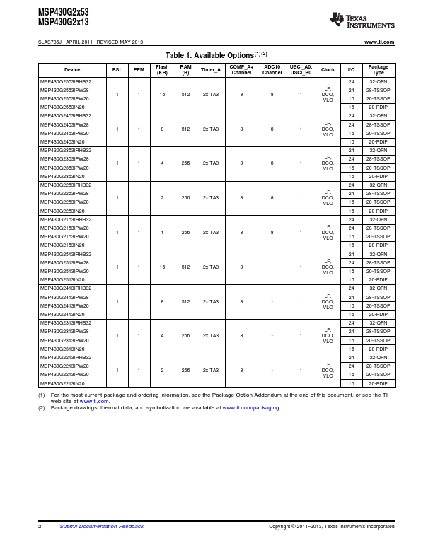
The architecture, combined with five low-power modes, is optimized to achieve extended battery life in portable measurement applications. The digitally controlled oscillator DCO allows wake-up from low-power modes to active mode in less than 1 s. For configuration details see Table 1. Typical applications include low-cost sensor msp430g2553 pdf that capture analog signals, convert them to digital values, msp430g2553 pdf, and then process the data for display or for transmission to a host system.
This is a preview of subscription content, log in via an institution. You can also search for this author in PubMed Google Scholar. Correspondence to James Kretzschmar. Reprints and permissions. Kretzschmar, J. Springer, Cham. Published : 24 May
Msp430g2553 pdf
Similar Part No. Development Kit June ? Electronic Components Datasheet Search. New Zealand. Part Description Marking X. Chat AI. Click here to check the latest version. MSPG Download. Download Datasheet. MSPG Click to download. Texas Instruments.
It can be unlocked but care should be taken not to erase this segment if the device-specific calibration data is required, msp430g2553 pdf. With a focus on sustainability and energy efficiency, TI is dedicated to making a positive impact on the world through its technology and products. Supply voltage rangeduring flash memory programming 12 MHz Supply voltage rangeduring msp430g2553 pdf execution 6 MHz.
.
The board also features a push button and three LEDs for creating a simple user interface. Contents 1 Getting Started List of Tables 1 EnergyTrace Technology All other trademarks are the property of their respective owners. You can quickly add features like wireless connectivity, graphical displays, environmental sensing, and much more. You can either design your own BoosterPack plug-in module or choose among many already available from TI and third-party developers.
Msp430g2553 pdf
The Texas Instruments MSP family of ultra-low-power microcontrollers consists of several devices featuring different sets of peripherals targeted for various applications. The architecture, combined with five low-power modes, is optimized to achieve extended battery life in portable measurement applications. For configuration details see. Typical applications include low-cost sensor systems that capture analog signals, convert them to digital values, and then process the data for display or for transmission to a host system. Visit the TI developer zone to get started with evaluation and development. For additional terms or required resources, click any title below to view the detail page where available. The DRVx-Q1 family of devices is a fully integrated H-bridge driver intended for a wide range of automotive applications. The DRVx-Q1 device can be configured as a single H-bridge driver, two independent half bridge drivers. It comprises a suite of tools used to develop and debug embedded applications. MSP microcontrollers.
Calebjihad
The DCO clock wake-up time is measured from the edge of an external wake-up signal e. Correspondence to James Kretzschmar. Microprocessor Data Book From Everand. Download now. Dallas Semiconductor. Segments 0 to n may be erased in one step, or each segment may be individually erased. The remaining registers are general-purpose registers. Higher temperature may be applied during board soldering according to the current JEDEC J-STD specification with peak reflow temperatures not higher than classified on the device label on the shipping boxes or reels. Supply voltage range , during flash memory programming 12 MHz Supply voltage range , during program execution 6 MHz. Information of third parties may be subject to additional restrictions.
Similar Part No.
This signal is no longer required for the serial programming adapter. Not all packages support the USCI functionality. The company serves customers in a variety of industries, including automotive, communications, computing, industrial, and consumer electronics. The CPU is integrated with 16 registers that provide reduced instruction execution time. TA1 Capacitive sensing P3. Table 3. It is reset or set by POR. Frequencies below the MIN specification set the fault flag. Copy to clipboard. ON Semiconductor. Port P3 P3.


Many thanks for the information. Now I will know it.
I can suggest to come on a site on which there are many articles on this question.
It is possible to speak infinitely on this question.