Danfoss vfd fault codes
The frequency converter is an electronic motor controller The operating guide is intended for use by qualified intended for: personnel. A power drive system consists of the attention to the safety instructions and general warnings.
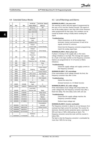
Safety note: To avoid electrical shock hazard- even after the power is disconnected- wait at least as follows before doing service on the frequency converter: V: 0. Warning Alarm Trip lock. The operation values shown on the display give detailed information about the status of the drive and the connected peripherals. These values are accessible also when warning and alarm messages are shown. RS or Profibus. Alarm with Trip lock An Alarm with Trip lock can be reset only after a complete mains off Display dark. If the drive is equipped with an external 24V supply D-option , it is enough to switch off mains and then reset the Alarm.
Danfoss vfd fault codes
.
Is this content inappropriate? Reduce the switching Par is too high frequency Par.
.
Troubleshoot and fix your Danfoss products to ensure smooth operations and high reliability. Find links below to useful resources for Drives, Cooling, Heating and Industrial Automation product portfolios. For AC drives please contact your local sales office for fix and troubleshooting by certified service partners. Find everything you need as a wholesale cooling professional , including easy-to-use tools, guides, and product information. Find everything you need as a heating professional , including product information, installation support and free training courses. Find everything you need as an industrial professional working with Danfoss Sensing Solutions, including product support, how-to videos and free training courses.
Danfoss vfd fault codes
Update your app to the latest version or download the app to your device for the latest content and offers. Investing in the future of your operations starts with securing your systems. All Drives must be currently covered by an active Danfoss Drive warranty to qualify for the extension. Registration submission must include the company name, email address, and phone number for where the Drives are installed. Embrace electrification at scale without compromise. See how you can run fully optimized applications that you can always rely on.
Restaurants in mollymook
Signal type current or voltage and signal level of the terminal 54 current input using the A DIP can be shown on the display. Check the reference sources the corresponding signal levels and their scaling can be shown on the display. The reference is too high 2. The active feedback signal is ences Auto Remote Trip interrupted or disturbed 2. Table 7. The motor coasts to a stop. When supplied from an isolated mains source IT regulations. The settings for the KTY Sensor 2. Check the mains for possible sation device over voltage. Warning Alarm Trip lock. Strip a section of the outer cable insulation. Bullet lists indicate other information. If the Function. As a start Wrong settings can lead to 0RPM 0.
Capacitor Reforming Procedure to condition the capacitors for the ideal Drives more than a year The capacitors will fully get drained out during its ideal time due to the internal ESR of the capacitor If we suddenly supply it with full voltage, there will be a high inrush charging current which leads to the breakdown of the capacitor In a normal scenario and for all the new drives, there is no need to do any additional precautions for Capacitor. But Capacitor conditioning can be carried out if the Drive was kept idle for more than a year The capacitors need to be slowly charged with controlled DC source and then only they can be used normally If DC source is not available then we can use series lamps for soft charge the drives with a small rating of MCB.
Options are programmed in Warning indicator light Alarm indicator light parameter Response to Mains Imbalance. Check allowed. Check the fuses to the frequency converter and mains power supply to the unit. Section VII. Wrong motor data 2. Academic Documents. Switching frequency set in 5. The bus line was interrupted 2. Check the mains for imbalance 4 Mains phase loss the imbalance is too high the voltage difference of the three phases must not exceed 3. The motor can start via an external Input power is cycled. Select current rating, the counter increases.


0 thoughts on “Danfoss vfd fault codes”